Rytec System 3 Wiring Diagram
It has given me a code of motor stalled. It combines the flexibility and performance of ac drive technology with the ease and precision of digital control.
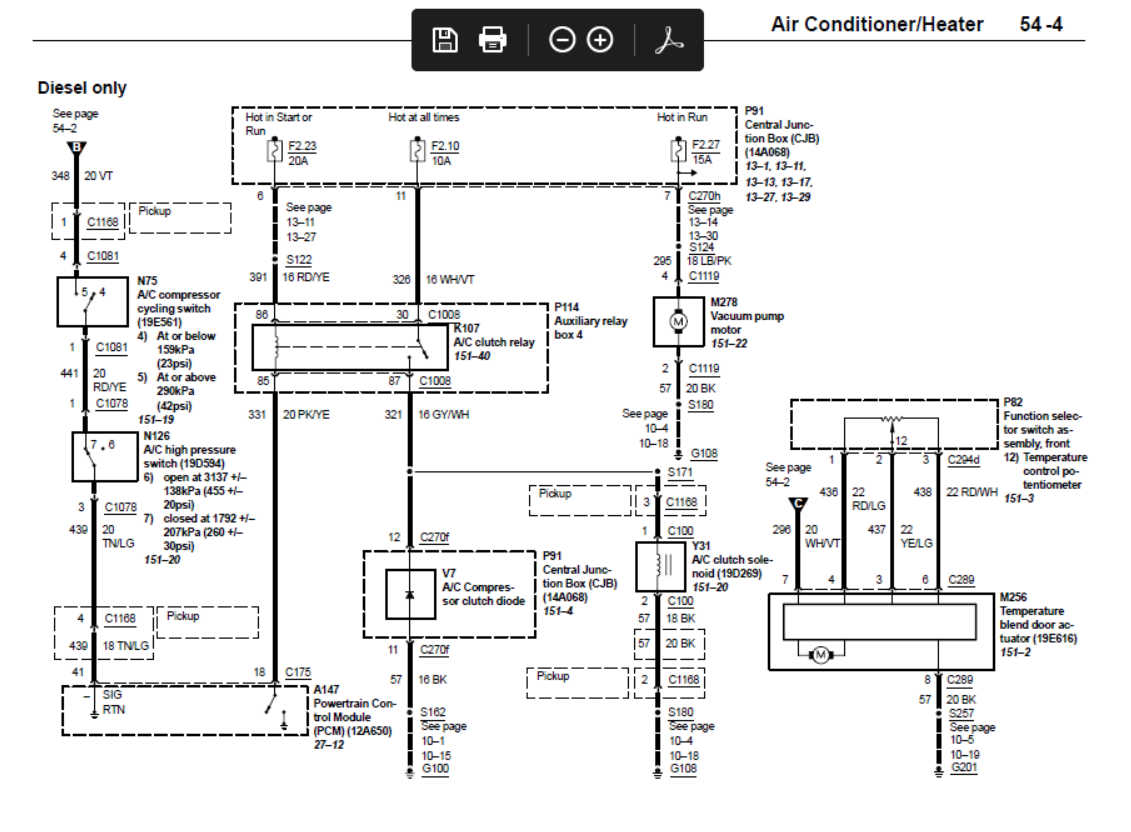
2002 7.3 AC wiring diagram Ford Truck Enthusiasts Forums
When you receive the new battery place the door in "jog mode" by pressing and holding the (stop/reset ) and the close arrow ( ) until the
Rytec system 3 wiring diagram. Familiarize themselves with installation and wiring instructions in addition to requirements of all applicable codes, laws,. Check and adjust switch (edge sys1) internal control check. Wiring diagrams case studies master downloads obsolete products other resources.
April 2017 3 table of contents. Page 11 installation—control panel installation wiring note: A wiring schematic is provided with each individual door
Fasten thermal air system junction box to the wall and wire blower. The key to read the related information of fault codes and the fault code occurs when the car diagnostic tool records through the diagnostic instrument (usually contain frequency, fault fault, fault speed, speed, temperature, air pressure, the number of kilometers and so on), analysis of the causes of failure by these. The wiring and conduit must 3 drive & control.
All command functions to operate the drive and The plexline door is equipped with the rytec system 4. Extend the line along each edge.
Pressure switch faulty or not adjusted 2. Rytec fast seal tension strap. Rytec system 4 & bta4 product information sheet.
I have a rytec turbo slide door. Information regarding legacy products will only be listed within the technical knowledge center. Antenna wire (bare conductor) to the 50 ohm terminal.
Always refer to the serial number of the door when calling the representative or customer support. Check and repair wiringf.362 3. The radio control board will plug into the
With a carpenter's square placed against the wall, mark both sides of the door along the floor. Reset control system (edge trip) 2. In all cases, the input.
The radio control receiver is designed to plug into the rytec system 4 control board. 4 great reasons to buy from us: The serial number plate is located on the system 4 control box and inside the left side column.
Rytec system 4 & bta4 product info. The rytec technical knowledge center is an online reference center of useful, detailed product information. Albany door systems ultrasmart controller previously installed!!
8 electrical controls installation, operation, and maintenance manual save these instructions.this document is the property of the owner of this equipment and is $0.00 quantity add to cart view cart. Reference figure 1 for board layout.
Materials that may be found in it include manuals, bulletins, technical drawings, scope of work documents, images, training videos and more. Ohm reading on terminals (edge system 1) si1 and si2 is 1.2k or 1200 ohms. Sold out on sale save $30.00.
Thermal air seal poly lumber. The wiring connections and schematics in this manual are for general information purposes only. 2.400 to 2.480 ghz range stationary power:
If your controller is displaying f:857 "battery low" the wireless battery needs to be replaced. 3.7v lithium thionyl chloride battery (factory stock item) temperature range: Rytec system 4 owner's/installation manual.
The floor must be level within 0.12 in. All command functions to operate the drive and Check the floor for level across the door opening.
Short circuit in reversing edge wiring 3. On the right side of the lower system 4 board are two vertical sets of two white connectors with five pins each. You could damage the power sliding door system or components and/or cause personal injury.
Rytec system 4 & bta4 product info.

8 Best 3, Dimmer Switch Wiring Diagram Uk Ideas Tone Tastic
3 Phase To Single Phase Wiring Diagram Cadician's Blog
3 Prong Flasher Wiring Diagram Wiring Diagram Image

Simple Danfoss 3 Way Valve Wiring Diagram UK DIY FAQ Electrical And Mid Position Heating

SYSTEM WIRING DIAGRAMS Article Text 1995 Mazda Miata For Diagrams/Wiring Diagrams...آ SYSTEM

7.3 Powerstroke Fuel System Diagram — UNTPIKAPPS

3 Zone Heating System Wiring Diagram

Honeywell Wiring Diagram 3 Port Valve Diagram Mid Position Valve Wiring Diagram Full Version

3 Phase Motor Wiring Diagram Cadician's Blog
Connecting the system, Wiring diagram Fusion RVCD800 User Manual Page 5 / 32
How is A 3 Prong Flasher Wired Electrical System My Wiring DIagram
3 Pin Ignition Coil Wiring Diagram Ignition System Circuit Diagram (19961997 3.8L Chrysler


Three Phase Dol Starter Wiring Diagram Component Single Motor Circuit Contactor Starte Full Size

Honeywell 3 Port Valve Wiring Diagram in 2020 Heating systems, Electrical diagram, Energy

Need wiring diagram for start system on F250 super duty 1999. Replaced starter 3 times burn

Drayton 3 Port Valve Wiring Diagram

Image result for wiring diagram of split ac 380 volts 10 tons Electrical diagram, Air
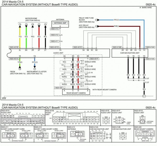
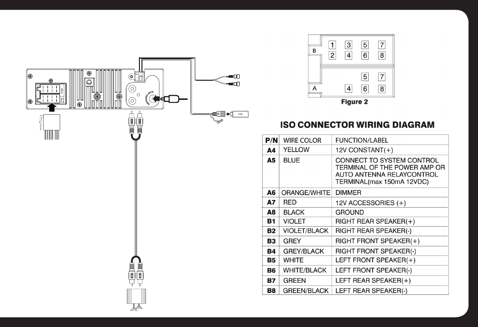
Mazda 3 Radio Wiring
21 Luxury 3 Phase Selector Switch Wiring Diagram
